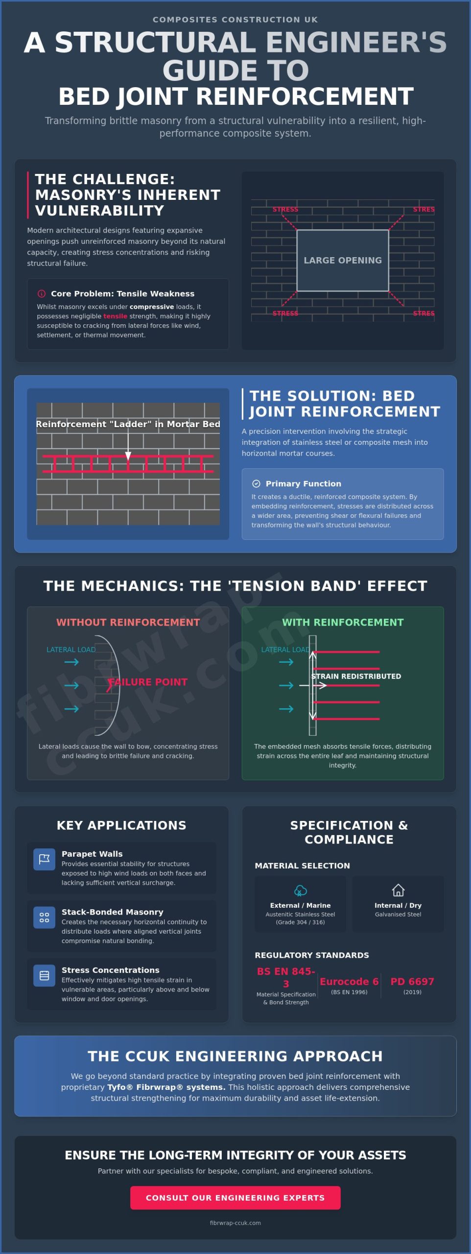
Could the forecast 7% increase in brick deliveries throughout 2026 expose a critical vulnerability in modern masonry design, or are we prepared to manage the resulting stress concentrations? Whilst masonry remains a foundational element of UK infrastructure, the architectural preference for expansive openings often pushes unreinforced walls beyond their lateral load capacity. You’ve likely faced the challenge of mitigating cracks at window corners or struggled to ensure that your specifications remain fully compliant with PD 6697:2019. The integration of bed joint reinforcement isn’t merely a secondary consideration; it’s a fundamental engineering requirement for ensuring long-term structural integrity.
This guide provides a comprehensive engineering analysis of how bed joint reinforcement functions as a precision intervention, transforming brittle masonry into a resilient composite. We’ll outline a methodical framework for professional installation that adheres to Eurocode 6 standards whilst exploring the structural mechanics that govern lateral stability. By following this expert-led approach, you’ll gain the technical clarity needed to specify bespoke solutions that extend the life-cycle of essential assets through proven science and engineering rigour.
Key Takeaways
- Analyse the mechanics of tensile strength and the ‘tension band’ effect required to redistribute strain and resist lateral forces within masonry leaves.
- Master the professional installation protocol for bed joint reinforcement, focusing on the precision of mortar bed thickness to guarantee structural bond integrity.
- Ensure regulatory compliance by applying the design specifications of BS EN 1996 and PD 6697:2019 to calculate reinforcement areas accurately.
- Explore the integration of traditional masonry reinforcement with proprietary Tyfo® Fibrwrap® systems for comprehensive structural strengthening and asset life-extension.
What is Bed Joint Reinforcement in Structural Engineering?
Within the discipline of structural remediation, bed joint reinforcement is defined as the strategic integration of prefabricated stainless steel or composite mesh into the horizontal mortar courses of a masonry leaf. This intervention is designed to address the inherent lack of tensile strength in unreinforced masonry, effectively transforming a brittle assembly of units into a ductile, reinforced composite. By embedding these reinforcement ladders or coils, engineers can ensure that localised stresses are distributed across a wider area, preventing the development of catastrophic shear or flexural failures. The fundamental Masonry construction principles dictate that whilst units such as brick or block excel under compressive loads, they remain vulnerable to tensile forces generated by thermal movement, ground settlement, or wind pressure.
Material selection is a critical factor in ensuring the longevity of the reinforcement. For external masonry leaves, the use of austenitic stainless steel, specifically Grade 304 or Grade 316 for marine environments, is mandatory to prevent expansive corrosion which can lead to further masonry spalling. Whilst galvanised steel options exist, they’re typically reserved for internal applications where the risk of moisture ingress is negligible. The primary mechanical function of bed joint reinforcement is the provision of lateral resistance, making it an essential specification for:
- Parapet walls: These structures are often exposed to high wind loads on both faces and lack the vertical surcharge required for stability.
- Stack-bonded masonry: Because the vertical joints align, there’s no natural overlap to distribute loads; reinforcement provides the necessary horizontal continuity.
- Stress concentrations: Areas above or below window and door openings frequently experience high tensile strain, which reinforcement effectively mitigates.
The Role of Reinforcement in Masonry Remediation
The application of bed joint reinforcement allows for the design and stabilisation of significantly larger masonry panels without the requirement for additional intermediate piers or wind posts. In the context of structural strengthening, it provides a methodical solution for collar-jointed and cavity walls, where it’s utilised to manage the differential movement between leaves whilst maintaining the overall integrity of the facade. This approach facilitates a transition from traditional, gravity-reliant masonry to high-performance reinforced structural systems that can withstand modern environmental demands.
Key Performance Standards: BS EN 845-3
Current specifications for these materials are governed by the BS EN 845-3 framework, which dictates rigorous requirements for longitudinal wire geometry and cross-wire spacing. A primary focus of this standard is the verification of bond strength between the reinforcement and the mortar; if the wire diameter is too large relative to the joint thickness, the bond is compromised, leading to slippage. The transition from the legacy BS 5628 standard to the comprehensive Eurocode 6 (BS EN 1996) has refined the way engineers calculate the required cross-sectional area of steel to ensure compliance with modern safety factors.
The Mechanics of Tensile Strength and Lateral Load Resistance
The mechanical efficacy of bed joint reinforcement rests on its capacity to function as a continuous tension band within the masonry matrix. Whilst unreinforced masonry possesses high compressive strength, its ultimate tensile capacity is negligible, often leading to brittle failure under minor flexural stress. When embedded, the reinforcement mesh absorbs these tensile forces, redistributing strain across the entire length of the masonry leaf rather than allowing it to localise at a single point of failure. This mechanical interaction relies on the shear bond between the mortar and the steel or composite wires, where the mortar acts as the essential medium for load transfer. By resisting flexural tension caused by wind pressures or subtle foundation shifts, the reinforcement ensures the wall behaves as a coherent, reinforced structural unit.
This “tension band” effect is particularly vital when masonry is subjected to out-of-plane loading. In these scenarios, the reinforcement provides the necessary internal resistance to prevent the masonry from bowing or collapsing. The interaction between the units and the mesh creates a composite material that maintains its integrity even when the mortar’s own bond strength is exceeded. Engineers seeking to optimise the performance of these systems across complex facades may benefit from a professional structural design feature to ensure all load paths are correctly identified and reinforced.
Controlling Stress Concentrations Around Openings
Structural openings for windows and doors represent significant discontinuities in a masonry panel, creating primary failure points where stresses naturally concentrate. To mitigate the risk of diagonal cracking at these corners, a specific placement strategy is required. The established engineering practice involves installing bed joint reinforcement in the first and second courses both above and below every opening. A critical component of this protocol is the 600mm rule; the reinforcement must extend at least 600mm beyond the edge of the opening to dissipate tensile strain effectively into the surrounding masonry mass. This ensures that the energy which would typically cause a crack is instead spread across a larger, more stable area of the wall.
Differential Movement and Thermal Expansion
Differential movement remains a persistent challenge in large-scale infrastructure, particularly where masonry is utilised as an infill for concrete frames. These materials possess disparate thermal expansion rates, which can induce significant internal stress. High-performance bed joint reinforcement minimises the visible impact of such movement by controlling crack widths, ensuring they remain micro-fine and structurally insignificant. Whilst reinforcement provides internal control, it must be used in conjunction with properly specified Movement Joints in Brickwork to accommodate larger volumetric changes. This dual approach of internal reinforcement and external joints is the standard for modern, resilient masonry design.
How to Install Bed Joint Reinforcement: A Professional Procedure
The transition from structural design to site execution requires a disciplined adherence to established engineering protocols. Whilst the theoretical benefits of bed joint reinforcement are well-documented, the actual performance of the masonry leaf is entirely dependent on the quality of the mortar bond and the precision of the mesh placement. Before any material is applied, the masonry course must be meticulously cleared of all loose debris and dust; a contaminated surface will inevitably lead to a bond failure that compromises the entire strengthening system. This preparation is a foundational requirement for achieving the empirical results expected in modern structural remediation.
A consistent mortar bed thickness, typically maintained between 10mm and 12mm, is essential for providing the necessary volume for full encapsulation. The reinforcement shouldn’t be laid directly onto the dry masonry units. Instead, it must be pressed firmly into a fresh layer of mortar. This ensures that the longitudinal and cross-wires are completely surrounded by the cementitious matrix, facilitating the load transfer mechanisms required for lateral stability. To maintain the continuity of the tension band, sections of reinforcement must be overlapped by a minimum of 150mm to 225mm, adhering to the recommendations set out in PD 6697:2019.
Step-by-Step Installation Methodology
A methodical approach ensures that the reinforcement performs as a coherent structural element within the wall leaf:
- Step 1: Spread an initial, uniform layer of mortar across the bed joint to approximately half the total intended thickness.
- Step 2: Place the reinforcement mesh onto the mortar, ensuring it’s centred within the wall leaf with a minimum 20mm cover from the external face.
- Step 3: Apply the remaining mortar layer, using a trowel to ensure the mesh is fully encapsulated without any trapped air pockets.
- Step 4: Tool the joint to the required architectural specification once the mortar has reached the appropriate degree of firmness.
Common Installation Errors to Avoid
Failure to provide adequate lapping is a frequent oversight that creates a structural discontinuity, leading to localised failure under lateral load. If the mesh is positioned too close to the external face, the risk of “ghosting”—where the reinforcement pattern becomes visible through the joint—or accelerated corrosion is significantly increased. Voids within the mortar bed are equally hazardous; they create pathways for moisture ingress that can lead to freeze-thaw damage and the eventual degradation of the reinforcement’s structural integrity. For projects requiring complex remediation or bespoke specifications, reaching out for a professional structural survey can prevent these costly execution errors.
Design Specifications and Regulatory Compliance
Adherence to Eurocode 6 (BS EN 1996) is the requisite standard for the design of reinforced masonry structures within the United Kingdom. This regulatory framework necessitates a rigorous calculation of the required cross-sectional area of steel (As) per metre of wall height to ensure that tensile stresses are adequately managed. Engineers must determine the reinforcement density based on the specific load cases identified during the structural survey, ensuring the volume of steel is sufficient to resist the calculated bending moments and shear forces. The precision of these bed joint reinforcement specifications is what distinguishes a compliant structural remediation from a superficial repair.
Environmental durability is addressed through the selection of material grades based on exposure classes, ranging from MX1 for dry internal conditions to MX4 for masonry exposed to severe salt spray or aggressive industrial atmospheres. Whilst galvanised steel may suffice for MX1 environments, austenitic stainless steel is mandatory for MX2 to MX4 classes to prevent the risk of carbonation-induced corrosion. Where traditional steel interventions impose prohibitive weight loads or require invasive installation, carbon fibre reinforcement for masonry walls offers a high-modulus alternative that addresses these vulnerabilities without the architectural compromises associated with legacy methods. The integration of bespoke design and engineering calculations ensures that every component is selected with a focus on asset life-extension and long-term structural integrity.
Increasing Movement Joint Spacing
One of the primary technical advantages of incorporating bed joint reinforcement is the ability to extend the distance between vertical movement joints. In unreinforced clay masonry, the standard spacing for movement joints is typically limited to 10 to 12 metres; however, the strategic use of reinforcement can increase this spacing by up to 50% in specific conditions. This is achieved by redistributing the strain from thermal expansion and moisture movement across a larger masonry panel, thereby reducing the frequency of unsightly and maintenance-intensive vertical joints. For a broader analysis of these mechanisms, refer to our Technical Guide to Masonry Reinforcement.
Load-Bearing vs Non-Load-Bearing Applications
The density and positioning of reinforcement differ significantly between load-bearing walls and non-load-bearing cladding panels. In structural applications such as parapet walls or high-rise infill panels, the reinforcement must be designed to account for both self-weight and dynamic loading, including peak wind pressures that vary with building height. Non-load-bearing applications may focus more heavily on aesthetic crack control, yet they still require a methodical approach to ensure that any localised stresses do not lead to structural instability. Each design must be validated through empirical evidence to confirm it meets the safety factors required for modern infrastructure.
Ensuring that your project meets these complex regulatory requirements is essential for safety and compliance. If you require technical assistance with your project specifications, we invite you to contact our engineering team for a professional structural survey.
Specialist Masonry Stabilisation: The CCUK Engineering Approach
The CCUK methodology transcends the simple installation of hardware, favouring an integrated engineering system that addresses the root causes of structural instability. Whilst standard wire products are widely available across the UK, total stabilisation often requires the combined application of helical bars and bed joint reinforcement to create a multi-directional strengthening matrix. This approach is particularly effective for remediating complex failures where localised stress has already compromised the masonry bond. To ensure the efficacy of these interventions, the integrity of the existing mortar is verified through rigorous pull-off tests before any specification is finalised, providing the empirical data required for a high-confidence structural design.
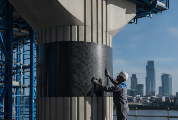
By integrating traditional masonry reinforcement with advanced Tyfo® Fibrwrap® systems, CCUK delivers a level of structural strengthening that standard methods cannot replicate. This synergy between carbon fibre reinforced polymers and stainless steel components is central to the concept of asset life-extension. It’s a philosophy that prioritises the sustainability of repair over the environmental and economic cost of demolition. With the UK construction industry forecast to grow by 3.7% in 2026, the demand for sophisticated remediation that preserves and strengthens existing infrastructure is set to intensify amongst asset managers and engineers.
Bespoke Remediation Strategies
In a 2025 project involving a historic masonry facade, CCUK engineers designed a bespoke solution that utilised concealed reinforcement to restore lateral resistance without altering the building’s aesthetic character. The advantage of engaging a design-and-install contractor lies in the seamless transition from technical analysis to site execution, ensuring that the theoretical performance of the bed joint reinforcement is fully realised in the final build. CCUK ensures that every structural intervention meets the highest safety and longevity standards through a disciplined adherence to current British and European engineering codes. This expert-led approach provides the absolute reliability required for high-consequence infrastructure projects.
Contacting a Specialist Engineering Contractor
When structural challenges exceed the scope of general property maintenance, it’s essential to move from a general builder to a specialist structural repair firm that understands advanced materials science. For large-scale masonry projects, requesting a feasibility study is the first step in identifying the most cost-effective and durable remediation path. This methodical assessment prevents the application of superficial repairs that fail to address underlying mechanical vulnerabilities. To discuss the specific requirements of your infrastructure asset and ensure its long-term security, Contact Composites Construction UK for a technical consultation on your next project.
Securing the Future of Masonry Infrastructure
The integration of bed joint reinforcement represents more than a remedial necessity; it’s a fundamental requirement for the resilience of the UK’s built environment. This guide has examined the transition from brittle masonry to a ductile composite, highlighting the technical precision required in both specification and site execution. By mitigating the vulnerabilities associated with stress concentrations and lateral pressures, engineers can ensure that masonry assets remain structurally sound throughout their intended design life. It’s through this methodical application of structural mechanics that the longevity of essential infrastructure is guaranteed.
As the industry anticipates a 3.7% growth in construction output through 2026, the priority shifts toward the sophisticated stabilisation and life-extension of existing assets. Composites Construction UK remains at the forefront of this field as the exclusive UK licensee for Tyfo® Fibrwrap® systems, providing expert engineering design and installation for national infrastructure projects. Our approach ensures that every intervention is grounded in empirical evidence and professional rigour, reflecting our role as guardians of structural safety. Consult our specialist engineering team for bespoke masonry reinforcement solutions to secure your next project with absolute reliability.
Frequently Asked Questions
What is the primary purpose of bed joint reinforcement?
The primary purpose is the enhancement of the masonry’s tensile strength to resist lateral forces and distribute localised stress concentrations. Unreinforced masonry is naturally brittle and vulnerable to shear; the reinforcement acts as an internal tension band. This mechanism ensures that strain is redistributed across the wall leaf, preventing the development of catastrophic fractures under environmental loading or minor ground movement.
Can bed joint reinforcement be used in both internal and external walls?
Yes, it’s suitable for both internal and external applications, provided that the material grade is selected according to the specific exposure class. External leaves require high-grade stainless steel to resist moisture-induced corrosion. Internal walls, which are typically classified under the MX1 exposure class, may utilise galvanised steel if the environment remains permanently dry and free from aggressive chemical ingress.
How much should bed joint reinforcement overlap?
A minimum overlap of 150mm to 225mm is required to maintain the structural continuity of the reinforcement run. This specification follows the recommendations set out in PD 6697:2019 for ensuring effective load transfer across separate sections. Failing to provide this overlap creates a structural discontinuity, which can lead to localised failure and crack formation when the masonry leaf is subjected to lateral pressure.
Is stainless steel reinforcement always necessary for masonry?
Stainless steel is mandatory for all masonry exposed to moisture or aggressive environments, classified as exposure classes MX2 through MX4. Grade 304 or 316 stainless steel prevents expansive corrosion that would otherwise cause the mortar joints to fail and the masonry to spall. Galvanised alternatives are only permissible in strictly dry, internal conditions where the risk of carbonation and moisture contact is non-existent.
Does bed joint reinforcement replace the need for movement joints?
No, reinforcement doesn’t eliminate the requirement for movement joints, though it can increase the permissible spacing between them by up to 50%. Whilst bed joint reinforcement manages internal tensile strain from thermal expansion, vertical movement joints are still necessary to accommodate larger volumetric changes in long masonry runs. It’s a dual-strategy approach that ensures the long-term stability and aesthetic integrity of the facade.
Can reinforcement be retrofitted to existing masonry walls?
Yes, reinforcement can be retrofitted through the installation of helical bars into pre-cut grooves in the existing mortar joints. This process, which is a core part of structural remediation, restores the integrity of a compromised wall without requiring demolition or replacement of the leaf. It’s a key component of asset life-extension, allowing historic or damaged infrastructure to meet modern safety standards through scientific engineering.
What is the difference between ladder-type and truss-type reinforcement?
Ladder-type reinforcement consists of parallel longitudinal wires connected by perpendicular cross-wires, whereas truss-type utilises a zig-zag internal wire configuration. In the UK, ladder-type is preferred for its ability to accommodate differential thermal movement whilst ensuring the cross-wires don’t interfere with the vertical cores of blocks. The choice depends on the specific rigidity requirements and the type of masonry units being utilised in the build.
How does bed joint reinforcement improve wind load resistance?
It improves wind load resistance by transforming the masonry panel into a reinforced composite that can withstand out-of-plane bending. The reinforcement absorbs the flexural tension generated on the leeward side of the wall during high-wind events. This increased lateral capacity allows for the design of larger, unsupported masonry panels that remain fully compliant with the safety factors defined in BS EN 1996.