


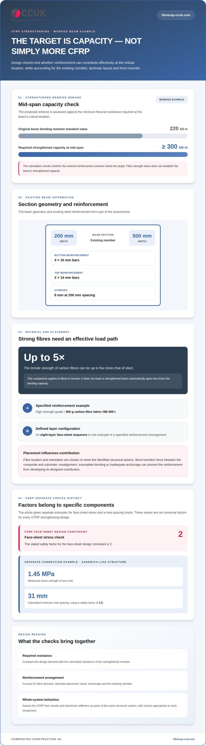
The decisive question in bending strengthening is not simply how much CFRP can be added, but where it can contribute effectively to the required capacity. In the worked beam example, the strengthening target is at least 300 kN·m at mid-span, against an original beam bending moment standard value of 220 kN·m. CFRP design calculations assess whether a proposed reinforcement scheme can meet that target and examine stress in the CFRP face sheets and aluminium stiffeners.
That assessment depends on more than the material’s tensile properties. The existing member and reinforcement, required capacity, and proposed CFRP layout all influence the design. Correct placement is central to understanding how the strengthening system will perform.
This article explains how designers establish the required bending capacity, account for CFRP reinforcement placement, and assess stresses in composite face sheets and aluminium stiffeners. It also shows how these checks work together when evaluating a strengthening scheme.
Key Takeaways
- Define the required bending capacity in relation to the beam’s existing demand, then assess whether the proposed strengthening scheme meets that target.
- Plan CFRP placement around the member’s bending behaviour and the reinforcement layout, rather than treating material quantity as the only design decision.
- Assess stress in the CFRP face sheets and aluminium stiffeners as parts of the same structural system, applying the stated safety factor to the face-sheet check.
- Use the design calculations to inform whether CFRP strengthening is suitable, and how specialist design and installation can support the structure’s continued use.
Required strengthened bending capacity
In CFRP design calculations, the required capacity is the bending resistance the strengthened member must provide under its design demand. The material properties and safety factors depend on the component being checked: the beam example uses a target of 300 kN·m at mid-span, while the rivet-spacing example uses a factor of 1.5.
Strengthened bending demand
Required strengthened bending capacity is the minimum flexural resistance specified for the member after reinforcement. It matters because the proposed composite laminate must provide adequate resistance at the critical location, not merely add carbon to the surface. In the example, the beam must achieve at least 300 kN·m at mid-span, compared with an original beam bending moment standard value of 220 kN·m.
The design check assesses whether the entered reinforcement scheme meets that target. The beam geometry and existing steel reinforcement form part of the assessment: the example has a 200 mm width, a 500 mm depth, four 16 mm bottom bars and two 14 mm top bars. Its 8 mm stirrups are spaced at 200 mm.
CFRP tensile strength and steel
Carbon fibres used in CFRP can have tensile strength up to five times that of steel. This comparison applies to the fibres in tension; it does not mean a strengthened beam automatically gains five times the bending capacity. The resin matrix, fibre direction, laminate placement and force transfer into the substrate all affect the composite’s contribution.
This distinction matters when selecting the material properties for a calculation. High fibre tensile strength is useful only if the reinforcement can develop its force and work with the existing member. The concrete strength grade therefore informs the assessment of the substrate and its interaction with the strengthening system.
Design equations and safety factors
Design equations compare the member’s bending demand with its calculated resistance, taking account of the existing section and proposed reinforcement. Concrete strength grade informs the concrete contribution, while CFRP tensile properties and placement affect the added flexural resistance. The check must consider the behaviour of the whole strengthened section, not treat fibre strength as a direct capacity multiplier.
Safety factors apply to the relevant design check, not as a universal value for every CFRP component. In the investigated sandwich-like structure, one rivet had a measured shear strength of 1.45 MPa; the calculated minimum rivet spacing was 31 mm using a safety factor of 1.5. This example illustrates a specific connection check, not a general factor for beam strengthening.
CFRP reinforcement design and placement
Placement determines how a lightweight reinforced polymer contributes to structural capacity. The design must connect the proposed laminate to the member’s load path and account for the intended manufacture and installation processes.
CFRP reinforcement positioning
CFRP reinforcement positioning means choosing the fibre location and orientation to resist the structural actions identified in the design. In flexural strengthening, fibres are positioned to contribute where tensile demand occurs, and the bond transfers force between the composite and the substrate.
The example specifies high-strength grade I 300 g carbon-fibre fabric HM-300-I. An eight-layer face-sheet sequence is another example of how a design defines reinforcement configuration. CAD and FEM software can support calculations of the proposed arrangement, allowing material mechanics and manufacturing constraints to inform the layout.
Placement errors can undermine the intended force transfer. Misaligned fibres, incomplete bonding or inadequate anchorage can keep the reinforcement from developing its designed contribution. The assessment should therefore account for substrate condition and installation quality.
Shear strengthening and anchorage
Shear-strengthening checks assess whether the reinforcement and its anchorage can transfer forces across potential shear regions. A flexural design alone does not establish that the member’s shear response or the reinforcement’s end connections are adequate.
Review the member’s shear demand, the proposed CFRP orientation and the available bond or mechanical anchorage. Check force transfer at terminations and changes in geometry, where local debonding or stress concentrations may affect performance. Treat the connection as part of the complete structural system.
Exposure, durability and fire resistance
Exposure assessment considers how environmental conditions and fire may affect the CFRP system, including its resin matrix, bond and supporting substrate. The system’s structural contribution depends on these components continuing to transfer force in service.
For durability, assess moisture, chemicals, temperature and substrate condition against the project environment, then define suitable protection and inspection provisions. For fire resistance, evaluate the complete strengthened assembly against the project’s performance requirements; fibre tensile properties alone do not establish the assembly’s fire behaviour. A project-specific design assessment can bring placement, anchorage and exposure considerations together.
Stress calculations for CFRP face sheets and aluminium stiffeners
Stress checks show how applied loads are shared between CFRP face sheets and aluminium stiffeners. Strain limits, bond behaviour and failure modes are assessed by comparing calculated demands with relevant material constraints; the face-sheet design constraint uses a safety factor of 2.
Strain limits and debonding
Strain checks compare deformation in the CFRP face sheet with its design limit, while debonding checks examine force transfer at the interface. Both are important: a face sheet may have adequate tensile properties but contribute ineffectively if the bond cannot transfer load.
For the face sheet, the calculation relates applied force to its effective area and considers the fibre direction. Under bending, the stress distribution also depends on the section’s geometry and position relative to its neutral axis. The safety factor of 2 is a stated constraint for face-sheet stress, not a universal factor for every component or failure check.
At the interface, assess whether stress concentrations could initiate separation from the concrete or another substrate. Surface condition, adhesive behaviour and termination details all affect this load path. Consider strain demand and bond resistance together, rather than treating the laminate as an isolated material.
CFRP failure modes
Failure-mode checks identify how the face sheet, bond, stiffener or supporting member could lose its structural function. Considering only CFRP tensile stress may overlook a weakness elsewhere in the assembly that controls performance.
For a CFRP face sheet, examine fibre rupture, matrix-related damage and debonding as distinct potential modes. For an aluminium stiffener, compare calculated stress with the relevant material properties and assess how its connection transfers load. The example stiffener is a square hollow section measuring 30 mm × 30 mm × 2 mm.
Stress in that section depends on applied force, bending effects and the hollow cross-section’s properties. Use the section dimensions when determining its effective area and resistance; do not treat the stiffener as a solid 30 mm square. Finally, assess whether the concrete or existing structure remains capable of carrying the redistributed actions. These checks connect face-sheet stress, stiffener behaviour and substrate response within one construction assessment.
What design equations apply to CFRP flexural strengthening of reinforced concrete beams?
Flexural design checks whether a strengthened reinforced-concrete beam’s calculated resistance meets its required bending demand. For CFRP sheets bonded to a beam, the calculation accounts for the existing concrete section, internal steel reinforcement and added composite reinforcement. It also examines the strain-compatibility and force-transfer assumptions used to calculate resistance.
Internal tensile and compressive forces must balance. Flexural resistance comes from these forces acting through their lever arms: conceptually, moment resistance equals force multiplied by its perpendicular distance from the compression resultant. To calculate the CFRP contribution, consider its stress and effective area together; concrete and existing steel contribute according to their positions and strains.
Strain compatibility links the beam’s curvature to strain at each material level. The calculation uses those strains and the relevant material properties to determine stress, then checks that the assumed force distribution satisfies equilibrium. In a scheme using bonded carbon-fibre fabric, the sheet’s position and fibre direction affect its effective contribution. The section’s neutral axis also matters because it separates the tensile and compressive regions.
A complete assessment compares calculated moment resistance with the required demand, then evaluates the limits that could govern first. These include CFRP strain, concrete compression, steel response, bond and anchorage, alongside shear capacity. The design should not treat the sheet’s tensile strength as the beam’s final resistance: the substrate and force-transfer mechanism also matter. A calculation sheet can record the geometry, material properties, assumptions and checks, making the design basis traceable. For a project-specific assessment of CFRP strengthening, discuss your strengthening design.
Composites Construction UK: Carbon Fibre Reinforced Polymer (CFRP) Strengthening
Composites Construction UK provides Carbon Fibre Reinforced Polymer (CFRP) Strengthening for structures requiring increased capacity or rehabilitation. When calculations indicate that a member needs strengthening, its team can support the next stage through feasibility studies, bespoke design solutions and professional installation.
The checks above help define the strengthening requirement, but the final scheme must also suit the existing structure and project conditions. Tyfo® Fibrwrap® Systems can be used for structural strengthening, while concrete repair may be needed where the substrate requires attention as part of the wider intervention. The appropriate scope depends on the structural assessment and the work required.
For a project-specific discussion of CFRP strengthening, contact Composites Construction UK.
Move from calculation to a considered strengthening plan
The next step is to apply the design to the structure’s actual condition, intended use and site constraints. CFRP design calculations provide a basis for this discussion, translating analytical requirements into a practical strengthening approach. When the assessment identifies a need for specialist intervention, keep the design and installation aligned with the same structural objectives.
Composites Construction UK provides Carbon Fibre Reinforced Polymer (CFRP) Strengthening, Tyfo® Fibrwrap® Systems and Blast Mitigation Systems. These services address structural strengthening and protection needs across different project contexts. A project discussion can bring together the required performance, substrate condition and proposed intervention, with the final approach based on the structure and its design requirements.
To discuss a strengthening project and its next steps, contact Composites Construction UK. A clear design brief is a practical starting point for moving towards a durable, carefully considered intervention.
Frequently Asked Questions
What is CFRP and when is it used for structural strengthening?
CFRP is a composite material made from carbon fibres embedded in a resin matrix, typically epoxy. It can strengthen concrete beams, columns and slabs when increased load-bearing capacity is needed without adding substantial structural weight. For example, externally bonded CFRP sheets can reinforce a beam’s tension zone. The design must account for the existing member, the bond to its substrate and the actions the strengthened element needs to resist.
What information is needed before calculating a CFRP retrofit?
Start by establishing the member’s geometry, support conditions, loading and intended use, then document its existing reinforcement and material condition. For a beam, useful records include its span, cross-section, reinforcement positions and concrete strength grade. Site investigation can identify deterioration or surface defects that may affect bonding. The design brief should also describe access, environmental exposure and operational constraints, as these influence the feasible reinforcement arrangement and construction sequence.
How do you calculate the required CFRP reinforcement area and number of layers?
First, calculate the additional tensile force needed to meet the required flexural resistance, accounting for the beam’s existing concrete and steel contributions. Divide this force by the design stress permitted in the CFRP to estimate the effective reinforcement area. Compare the required area per unit width with the fabric’s effective area per layer, using its specified properties. Before adopting a layer arrangement, check strain, bond, anchorage and failure modes.
Which UK standards and guidance apply to CFRP structural design, including Eurocodes and Concrete Society TR55?
Use the applicable UK design basis for the concrete member and its supporting structure, including relevant Eurocodes and UK National Annexes. Concrete Society TR55 provides specialist guidance for externally bonded FRP strengthening of concrete. Use the applicable design basis for the concrete member, and do not assume that a steel-design reference alone is sufficient for CFRP strengthening. The chosen basis should be stated in the calculation documentation.