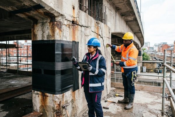


Multi-storey car park strengthening costs depend on the structure’s condition, the extent of concrete damage and corrosion, and the work needed to restore capacity or protect the asset. A condition survey helps establish the cause and scale of deterioration, so repairs and strengthening can be designed around the actual risks rather than assumptions.
It’s understandable to want a reliable budget before planning work, particularly when repairs may affect parking capacity and operations. The cost depends on the condition and scope, and is established after a quote request. Key influences include survey findings, access, surface preparation, repair quantities and the strengthening method selected.
This article explains how surveys identify concrete deterioration and reinforcement corrosion, how engineers assess decks, beams and columns, and when methods such as carbon fibre strengthening or concrete repair may be appropriate. It also outlines the main factors that shape project budgets, helping you understand the process from investigation to a defined scope of work.
Key Takeaways
- Use condition surveys to identify deterioration mechanisms, including chloride contamination and reinforcement corrosion, before defining repair work.
- The BS EN 1504 series is identified for the assessment and repair of concrete structures, according to the British Standards Institution.
- Strengthening methods for decks, beams and columns are selected according to the structural demand, access constraints and required intervention.
- Anchoring and near-surface-mounted solutions depend on the substrate condition and how loads need to be transferred into the structure.
- Build a realistic repair budget by considering survey findings, preparation, repair quantities, access and the specification required for the deck.
Concrete damage, chloride contamination and corrosion risk
In UK car parks, water, de-icing salts and traffic can damage reinforced concrete. A condition survey helps distinguish surface defects from corrosion risks that need structural assessment.
Assessing concrete condition and corrosion
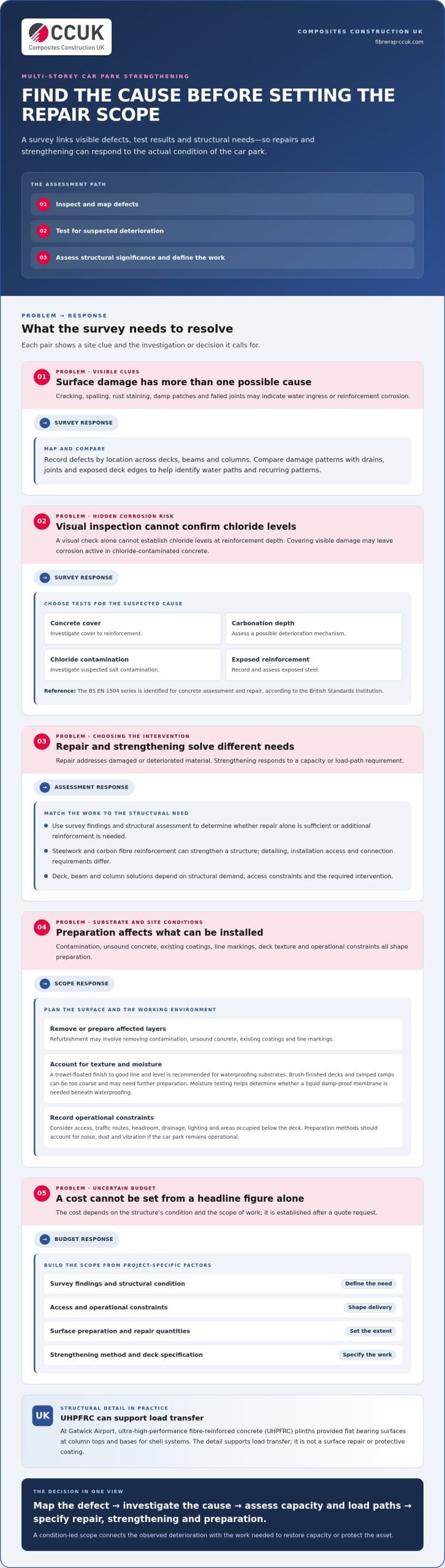
Inspectors map cracking, spalling, rust staining, damp patches and failed joints across decks, beams and columns. These signs can indicate water ingress or reinforcement corrosion, but visual inspection alone cannot establish chloride levels at reinforcement depth. The BS EN 1504 series is identified for concrete assessment and repair, according to the British Standards Institution.
A survey can combine visual inspection with tests chosen for the suspected cause of deterioration. Testing may assess concrete cover, carbonation depth, chloride contamination and exposed reinforcement. Findings should be recorded by location so damage patterns can be compared with drains, joints and exposed deck edges.
Comparing reinforcement and repair options
Concrete repair addresses damaged or deteriorated material, while strengthening responds to a capacity or load-path requirement. Steelwork and carbon fibre reinforcement can strengthen a structure, but their detailing, installation access and connection requirements differ. Survey findings and structural assessment determine whether repair alone is sufficient or additional reinforcement is needed.
In chloride-contaminated concrete, simply covering visible damage may leave corrosion active within the structure. Repair specifications need to address the affected concrete and reinforcement, as well as protection against further water or salt ingress. The extent of removal and reinstatement depends on mapped defects and test results.
Risks of delaying repairs or strengthening
Delay can allow water and de-icing salts to keep reaching reinforcement through cracks, failed joints or damaged coatings. Corrosion can cause further cracking and concrete loss, increasing the area that needs investigation and repair. If structural capacity is affected, deterioration may also lead to operational restrictions while the asset is assessed.
Early assessment helps identify the cause before repair boundaries are set. For example, failed deck joints can let water reach lower levels, where concealed reinforcement may corrode. Keep drains clear, and use regular wash-downs to help limit contaminant build-up.
Coating performance also depends on the substrate and its preparation. Refurbishment may require removing contamination, unsound concrete, existing coatings and line markings. The preparation method should account for noise, dust and vibration, particularly if the car park remains operational. Moisture testing helps determine whether a liquid damp-proof membrane is needed beneath waterproofing.
Deck texture affects coating preparation. A trowel-floated finish to good line and level is recommended for waterproofing substrates. Brush-finished decks and tamped ramps can be too coarse, requiring additional preparation before a waterproof coating is applied. Fully exposed decks need waterproofing specified for weather exposure and water ingress.
Ultra-high-performance fibre-reinforced concrete (UHPFRC) can form part of a strengthening detail. At Gatwick Airport, UHPFRC plinths provided flat bearing surfaces at column tops and bases for shell systems. This shows how a concrete element can support load transfer, rather than act as a surface repair or protective coating.
Condition surveys and structural assessments
A useful assessment connects observed defects with their likely cause, extent and structural significance. For a UK car park, this means reviewing records, inspecting accessible areas and selecting targeted tests before repair or strengthening is designed.
Start with available drawings, previous inspection reports, repair records and information about changes in use. These documents help the engineer compare the intended structural arrangement with current conditions. A site inspection can then map cracks, movement, water paths, damaged joints, exposed reinforcement and concrete loss. Recording each defect by location creates a practical schedule for further investigation.
Testing should address specific questions raised by the inspection. For example, local opening-up may reveal reinforcement details, while concrete tests can investigate material condition or contamination. The results are assessed alongside the structural form, observed movement and load paths. The assessment should establish whether the issue is local deterioration, a recurring defect or a capacity concern requiring strengthening.
Asphalt needs its own condition survey when planning refurbishment. Inspectors look for cracking, fretting, failed joints, ponding and depressions around wheel stands. These depressions, known as dishing, are usually described as four craters. Mapping their locations helps distinguish isolated surface damage from a pattern that may indicate movement or inadequate support beneath the asphalt.
Site conditions also shape the investigation. Surveyors should record traffic routes, headroom, access restrictions, drainage, lighting and areas occupied below the deck. These observations affect where testing can take place and how later works can be sequenced. If preparation may create dust, noise or vibration, the survey should identify nearby users and sensitive operations.
Before strengthening, bring together the condition survey, structural assessment, proposed design, work sequence and traffic-management arrangements. Agree the scope with the asset owner and establish which approvals apply to the proposed work, including planning or building-control requirements. The approvals depend on the nature and location of the work, so resolve them before construction begins.
Inspection findings can change the extent and urgency of refurbishment. Merry Hill’s Purple and Green multi-storey car parks closed in 2021 after failing a structural assessment, illustrating the operational importance of evaluating condition and capacity. Regular inspection and timely refurbishment help inform decisions about safe operation, repair priorities and commercial viability.
A clearly documented survey gives the design team a basis for prioritising repairs and comparing intervention options. Structural surveys can help define the next steps where defects or assessment findings indicate that further engineering work is needed.
Structural strengthening of decks, beams and columns
Strengthening design starts with the element’s structural function, measured condition and required load path. Decks, beams and columns each need a different intervention.
Strengthening decks and beams
For decks and beams, engineers assess whether the deficiency concerns bending, shear, local deterioration or load transfer. Externally applied L-shaped CFRP profiles can increase the shear capacity of reinforced concrete T-beams. The design must account for existing concrete, reinforcement layout, bond surface and anchorage, as these affect how strengthening forces enter the structure.
Deck strengthening also requires attention to vehicle loading and the intended use of each level. The intervention should integrate with waterproofing and drainage, rather than obstructing joints or creating new water paths. For beams, reinforcement location and direction should match the assessed structural demand.
Strengthening cracked columns
Cracks in a column need assessment of their pattern, width, location and relationship to loading before a strengthening detail is selected. At Gatwick Airport, three columns on the ground and first floors showed signs of overloading. The solution used shells bearing on UHPFRC plinths at the top and bottom, providing flat bearing surfaces.
This approach avoided demolition and props, and the car park did not need to close. After the plinths were built, installation and pre-loading of each shell system took around a week at most. The case shows how a designed load-transfer detail can address column capacity while limiting disruption.
Improving column flexural strength
Column flexural strengthening addresses bending demand, which may result from eccentric loading, restraint or changes in structural use. CFRP plates or fabric can provide additional tensile resistance when positioned and anchored to suit the design. The engineer assesses existing reinforcement, concrete condition and load path, then details the strengthening to transfer forces effectively.
Beam strengthening follows the same principle of matching reinforcement to structural action, but the required orientation and anchorage differ. A structural assessment should distinguish flexural demand from shear deficiency, since an intervention suited to one does not automatically address the other.
Meeting design standards and regulations
There is no single historic design code that can be applied to every car park strengthening project. CP110 was published in 1972, while BS8110 was published in 1985 and 1997; the design basis should account for the structure’s original standards and the requirements applicable to the proposed works. BS 8110 and Eurocode EC2 do not contain exposure conditions matching car park structures, so exposure needs explicit consideration.
For an existing structure, the engineer should document assumptions, loads, material properties, connections and the design standard used. This gives the asset owner a clear basis for reviewing structural capacity, building-control requirements and the proposed strengthening detail.
Programme and access depend on the number of elements, preparation, installation sequence and any loading restrictions. At Gatwick Airport, shell installation and pre-loading took around a week at most after the plinths were constructed, and the car park remained open during the project.
Future vehicle use should be included in the load assessment, alongside charging equipment and its support requirements. Sika research comparing the top five selling cars of the 1960s with the top five selling EVs in 2021 found a 148% vehicle weight increase. The design should therefore assess existing capacity against the intended future loads, rather than assume the original structure remains adequate.
Anchoring and near-surface-mounted strengthening
Anchors and near-surface-mounted (NSM) reinforcement transfer forces between strengthening materials and existing reinforced concrete. Their design depends on the substrate, load path and available installation space.
How anchorage transfers structural forces
An anchor connects a strengthening element to concrete, allowing forces to pass across the interface. The design must account for concrete condition, reinforcement layout, edge distances and loading direction. On a beam, for example, the anchorage must develop the reinforcement force without causing local concrete breakout or bond failure.
Before specifying anchors, the design team reviews drawings and survey findings, then locates existing reinforcement. This reduces the risk of drilling through bars or services. Anchor type, embedment and spacing are then designed for the required load transfer and actual substrate, rather than chosen as a generic detail.
Near-surface-mounted reinforcement
NSM strengthening places a reinforcing element in a narrow groove cut into the concrete surface, then fills the groove with a compatible bonding material. The method can provide a protected, flush installation where exposed reinforcement would obstruct vehicle clearance or car park use. Groove position and depth must suit the element’s geometry and avoid existing reinforcement.
Carbon fibre reinforcement can also be applied in lengths of up to 50 m in one go. Steel strengthening plates can have practical length limitations because of their fixings. These differing installation characteristics influence joint locations, anchorage details and the practical sequence of work.
Specifying the substrate and installation
Installation begins by confirming that the concrete surface can support the designed bond and anchorage. Contamination, weak material, coatings or surface irregularities can compromise contact, so preparation must follow the selected system’s requirements. The design should also account for moisture and exposure, particularly on decks subject to water ingress and de-icing salts.
For NSM work, the sequence includes setting out the reinforcement route, checking for embedded bars, cutting and cleaning the groove, placing the reinforcement and filling the recess. Each stage affects the final load transfer. At a car park beam, for example, poor groove alignment could interrupt continuity across the required strengthening zone.
Detailing for car park constraints
Anchoring details must suit the structure’s geometry and work area. Limited soffit access, overhead services, vehicle headroom and live traffic routes can influence whether surface-mounted plates or NSM reinforcement are practical. Where several beams or columns need treatment, consistent setting-out and sequencing help coordinate installation across the affected areas.
Inspect completed work against the approved design and installation requirements. Relevant checks include reinforcement position, anchorage installation, bond contact and local concrete condition. Recording these details provides an asset-management reference for future inspections and helps relate observed performance to the original strengthening design.
Selection is a structural decision, not simply a choice between steel and composite materials. The engineer matches the anchorage method to the required force transfer, substrate condition, access and operational constraints, then details connections so the strengthening works with the existing structure.
Repair specifications and budget costings
A reliable repair specification turns survey findings into defined work, measurable quantities and acceptance criteria. For a UK car park, the budget is shaped by concrete condition, access, preparation, repair extent, waterproofing requirements and operational constraints. The cost depends on the project and is established after a quote request. Key factors include survey findings, access, preparation, repair quantities and the specified system.
Define the scope before costing
Start by separating concrete repair from structural strengthening, since each addresses a different requirement. The specification should identify defect locations, removal limits, reinforcement treatment, reinstatement materials and inspection points. It should also set out how joints, drainage and deck edges will be treated, because these details affect whether water can continue reaching the structure.
Base quantities on mapped defects and measured work areas, not broad allowances alone. Isolated spalls, for example, require different removal and reinstatement quantities from widespread deterioration across a deck. Access equipment, traffic management, waste removal and work sequencing also affect labour and programme requirements.
Specify protection for exposure and use
Fully exposed multi-storey decks should have full waterproofing specified. Decks above retail, commercial or residential areas need protection against water ingress to lower levels, even when they aren’t directly exposed to weather. Intermediate or underground decks may use a more cost-effective concrete protection system without a membrane when their exposure conditions support that approach.
Moisture in the concrete should be rigorously tested before deciding whether a liquid damp-proof membrane is needed beneath waterproofing. A reinforced membrane system may be specified using EN 1062-7:2004 Method A (static)-A2 and EN 1062-7:2004 Method B (dynamic)-B4.2. The specification should identify the intended performance and relevant test method clearly.
Account for preparation and connections
Preparation can involve removing contamination, damaged concrete, existing coatings and line markings. The method affects dust, noise and vibration, so phasing should account for vehicle movements and occupied areas below. A trowel-floated finish to good line and level is recommended as a waterproofing substrate. Brush-finished decks and tamped ramps are too coarse for coating systems without additional preparation.
Where metal-to-metal contacts use bolted connections, their design should follow BS 5950 or another appropriate standard. Include connection details, installation tolerances and inspection requirements in the specification. Clear details reduce uncertainty during tendering and help ensure that quotations cover comparable work.
A cost plan should link measured quantities with preparation, protection, access and sequencing. Concrete repair requirements can be defined by setting out the repair scope and the structural information needed to specify it.
Composites Construction UK: Carbon Fibre Reinforced Polymer (CFRP) Strengthening
Composites Construction UK provides Carbon Fibre Reinforced Polymer (CFRP) Strengthening and Concrete Repair for car park structures where survey findings identify capacity or deterioration concerns. The appropriate intervention depends on the structural assessment: CFRP can strengthen existing elements, while concrete repair addresses damaged material and supports continued use of the structure.
Where findings point to strengthening, Composites Construction UK develops project-specific design solutions and provides professional installation, including Tyfo® Fibrwrap® Systems. The aim is to rehabilitate and upgrade the structure through a considered intervention, extending its functional life where repair and strengthening are suitable alternatives to replacement.
For a car park assessment or repair scope, contact Composites Construction UK to discuss the project.
Set a clear direction for your car park
The next step is to turn engineering findings into a prioritised scope, clearly defining performance requirements, sequencing and operational constraints. This gives asset teams a sound basis for planning multi-storey car park strengthening around the structure’s continued use, rather than treating each defect as an isolated repair.
Where the design calls for composite reinforcement, Composites Construction UK offers Carbon Fibre Reinforced Polymer (CFRP) Strengthening and Tyfo® Fibrwrap® Systems. Its services also include Blast Mitigation Systems, which address a distinct structural risk and are relevant only where the project requires them. The intervention should follow the engineering need and evidence gathered about the asset.
Discuss the assessment findings, design requirements and next steps with Composites Construction UK. A clearly defined project brief can help move the work from investigation towards a considered, durable intervention. Take the next step when you’re ready to plan the structure’s future.
Frequently Asked Questions
What are the common causes of structural deterioration in UK multi-storey car parks?
Water ingress, de-icing salts, carbonation, vehicle fluids and repeated traffic can contribute to deterioration. In a car park, leaking joints or blocked drainage can direct water into concrete, while chloride contamination can promote reinforcement corrosion. Damage often develops where moisture and contaminants repeatedly reach the structure, such as exposed deck edges or poorly protected joints. Identifying the ingress route helps distinguish the source from the visible defect.
How is a multi-storey car park assessed for structural condition and load capacity?
A structural assessment combines inspection, targeted investigation and engineering calculations. The engineer reviews available drawings, records changes in use, maps defects, and examines the structural arrangement and load paths. Where needed, testing can establish material properties or reinforcement details. Calculations then compare the structure’s capacity with the loads it must support, including proposed changes such as new equipment or altered vehicle use.
What strengthening methods are used for concrete multi-storey car parks?
Methods include externally bonded carbon fibre reinforcement, steel plates or sections, concrete repair, and additional concrete or composite elements. Selection depends on the structural deficiency, substrate condition, geometry, access and load-transfer requirements. For example, a beam requiring greater shear capacity needs different detailing from a column requiring confinement or a deck requiring flexural reinforcement. Repair and strengthening may be combined where deterioration and capacity concerns occur together.
How do engineers strengthen car park decks, columns, beams and ramps?
Engineers first identify the structural action requiring improvement, then detail reinforcement and anchorage to transfer forces into the existing element. Decks may need flexural strengthening, while beams may require additional shear or bending resistance. Column interventions can address axial or bending demand. Ramps also need assessment of their support, surface condition, vehicle loading and drainage, so strengthening details do not create new water paths or interfere with use.
How much does multi-storey car park strengthening cost per square metre in the UK?
A project price is established after a quote request, rather than through a single rate per square metre. The scope and budget are shaped by survey findings, the repair or strengthening method, quantities, substrate preparation, access, traffic management and waterproofing requirements. A measured specification helps distinguish local repairs from wider interventions and provides a clearer basis for comparing the work and its sequencing.
Which UK specialist contractors and structural engineers provide multi-storey car park strengthening?
Choose an engineering contractor whose work addresses the identified structural need, from condition investigation through repair or strengthening design and installation. Composites Construction UK provides structural strengthening and concrete repair, including Carbon Fibre Reinforced Polymer (CFRP) Strengthening and Tyfo® Fibrwrap® Systems. Its Structural Surveys and Testing can support investigations when concrete condition, reinforcement or capacity concerns need assessment before defining a repair scope.